 |
UaModeler
1.4.2.342
|
|
UaModeler
1.4.2.342
|
This example decribes how to create a new project and generate C# source files which can be used with the Unified Automation .NET Client SDK version 2.1 and higher.
The client connects to a server that provides a structured data type “Vector”. In this tutorial the parts of the information model used by a client (HowTo Use the Generated Files in a Visual Studio Project) will be defined. We expect that the server that the client will connect to, provides exactly this information model. Especially we expect that the server uses the same NamespaceUri, the same browse names and the same node ids. To ensure this, we will use the same model we create for the client to generate a Visual Studio server project.
This will now be explained in eleven simple steps.
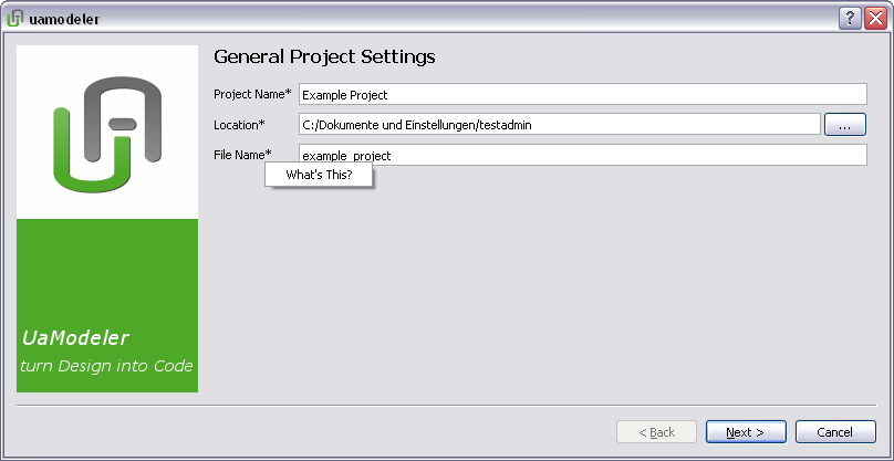
To create a new project, choose “File → New Project” from the menu bar. The “New Project” wizard will appear. Fill in a project name and a file name to your liking. For additional information on an input field, right click on its label and choose “What’s This?” from the context menu.
By default, the project will be generated in the user’s home directory. Feel free to chose a different directory for which you have read and write access.
After confirming the General Project Settings by pressing the button “Next”, the “Generate Code” dialog appears. Here you specify the Code Template Set and the Output Directory for the generated code. At “Template Set”, choose the kind of code to be generated, i.e. the SDK you intend to use the code with.
As output directory (i.e. the folder to store the generated files), choose a folder to your liking for which you have read and write access.

After confirming with “Next” the “Choose Base Model” dialog appears. Here you specify the different Base Models. The first NodeSet is the mandatory root namespace of the server. All other suggested models are optional. You can add your own model by clicking the button “Find another model”.

The last step of the wizard guides you to the “New Model” page. Here you specify the different information of your new model. Please fill out all fields as shown below.

In the Information Model Window on the left pane of the UaModeler you browse down to Types → DataTypes → BaseDataType → Structure. The new data type will be derived from Structure. Right click on Structure and select “Add New Structured DataType”.

The type definition document will show up in the middle of the UaModeler window. Expand the input fields at “Type” and fill in a name for the new structure (here “Vector”). All other information can be added later. Confirm by clicking on the “OK” button.

You can see the newly created node (Vector) in the Information Model Window below “Structure”. Select it to display its content in the main window.
In this example, we will add three fields, called “X”, “Y” and “Z”, all having the data type “Double”. By pressing the triangle next to “Children”, an input field shows up for adding fields. Click on “Add Name” to add a new field. Confirm by clicking on the “OK” button.

In the Information Model Window on the left pane of the UaModeler browse down to Types → ObjectTypes → BaseObjectTypes. The new object will be derived from BaseObjectTypes. Right click on BaseObjectTypes and select “Add New Type”.

The type definition document will show up in the middle of the UaModeler window. Expand the input fields at “Type” and fill in a name for the new object (here “MyObjectType”). All other information can be added later. Confirm by clicking on the “OK” button.

You can see the newly created node (MyObjectType) in the Information Model Window below “BaseObjectType”. Select it to display its content in the main window.
In this example, we will add two components to the Object Type, a variable of data type Vector (DemoVector) and one method (VectorAdd) with two input and one output argument, each having the DataType Vector.
By pressing the triangle next to “Children”, an input field shows up for adding node declarations. Clicking on “Select NodeClass” adds a new node. For chosing the DataType “Vector” (created in the previous step), select <Add another node ...> from the drop-down menu to open a browse window. The DataType “Vector” can be found in the tree below of “Structure”.

For adding input and output arguments to a method, click on the green triangle at the right end of the row. Confirm your changes by clicking on the “OK” button.

With the toolbar buttons you can switch between the model view and the type declaration view.

Right click on the “Objects” folder in the Information Model Window and select “Add Instance” from the context menu.

Expand the input fields at “Instance”, select “MyObjectType” as Type Definition, enter “MyObject” as name, and confirm with “OK”.

In the Information Model Window on the left pane of the UaModeler browse down to Types → EventTypes → BaseEventTypes. The new object will be derived from BaseEventTypes. Right click on BaseEventTypes and select “Add New Type”.

The type definition document will show up in the middle of the UaModeler window. Fill in a name for the object (here “MyEventType”) and confirm by clicking on the “OK” button.

In this example the Event Type will have two components, a variable with data type Int32 and a variable with data type Vector. Select the newly created Event Type in the Information model window, add the nodes to the input field at “Children” like shown in the screenshot below and confirm with “OK”.

With the toolbar buttons you can switch between the model view and the type declaration view.

When the design is completed you can generate the code for your model. It is possible to design multiple models in a project (each stored in a different file), but code generation is only performed for those that are marked as “Generate Namespace”, indicated by a blue gear-wheel symbol. The new model is pre-selected. You can select or deselect “Generate Namespace” by right clicking on the model node.

For generating the source files, press the “Compile” button (the blue gear-wheel) in the menu bar. When the compilation is finished you will find your generated *.cs files located in the output folder (as set in Step 2: Selecting a Template).

Congratulations—your design was turned into source code. Now you are able to integrate your created code into your client application.
Just one last step if you’d like to continue with the next HowTo: Generate a Default Server Application using the same model we created for the client. We will connect to this server in the section HowTo Use the Generated Files in a Visual Studio Project.
Select Project → Project Settings from the menu bar and select the .NET Server 2.1 templates. Continue with “Next”.

Fill out the next window as shown in the screenshot below. For more information on the input fields see the .NET Server tutorial.

Leave the next window unchanged and press “Finish”.

Press the “Compile” button and choose “Yes” when asked if already existing files should be overwritten. The generated files including a Visual Studio Project for a default server application can be found in the output folder.

Finally, right-click on the model in the Project Window and select Export XML. Copy the xml file to the output folder.
You are now ready to continue with the section HowTo Use the Generated Files in a Visual Studio Project.

